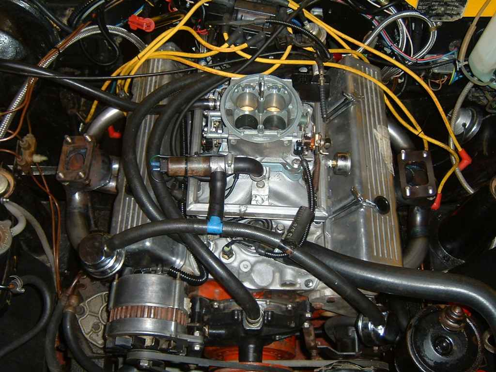
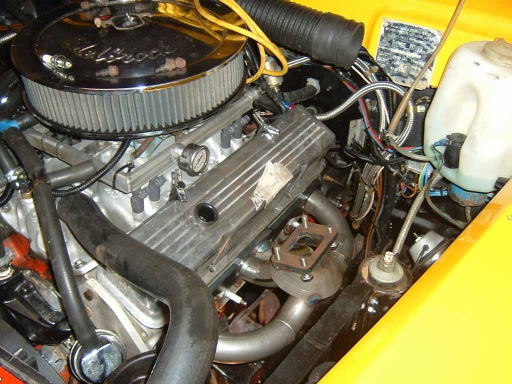
Twin turbocharged 350 Chevy project
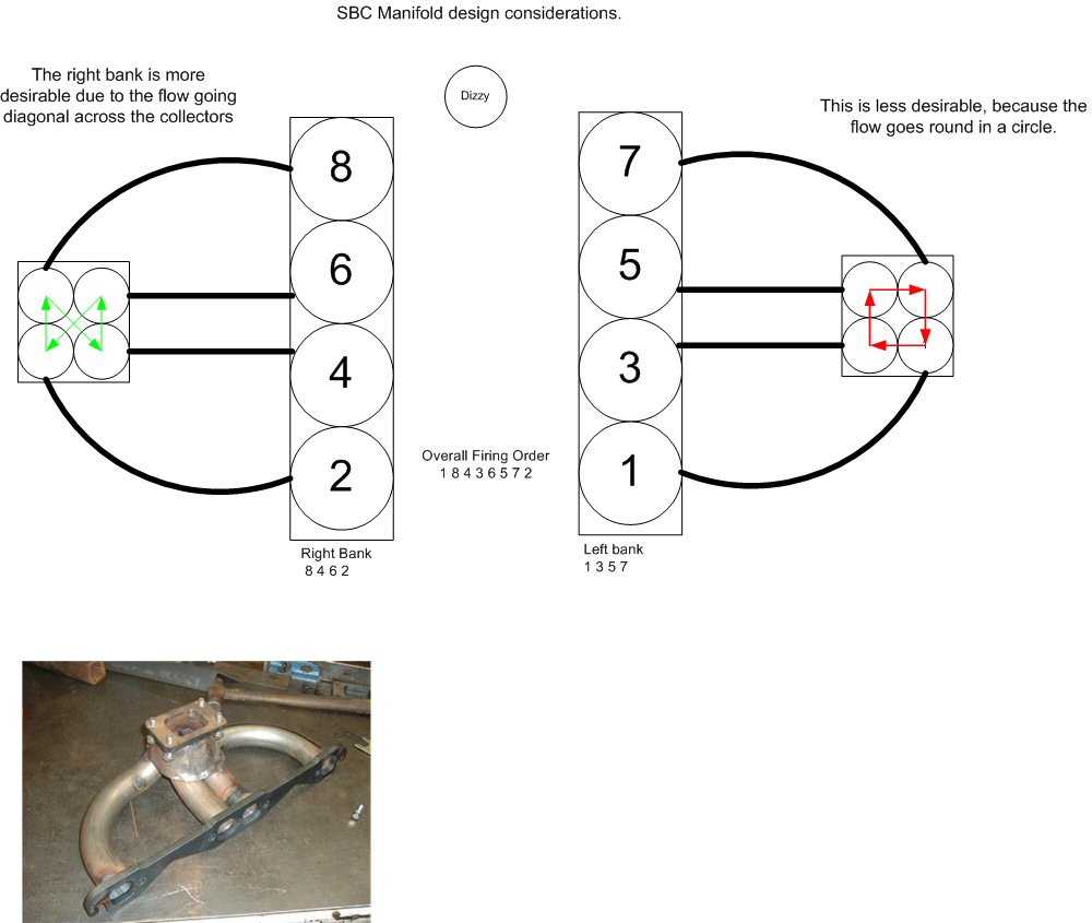
Turbo Header Design Considerations
Had an interesting chat with Giles at Turbotechnics -
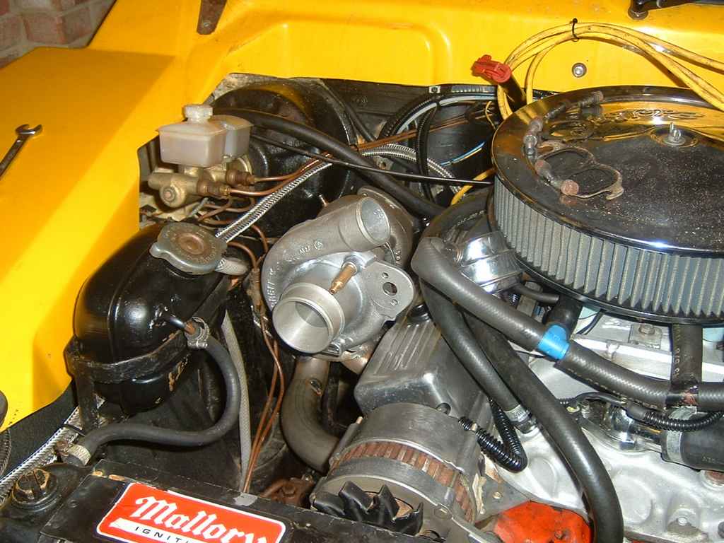
Nearside turbo fabrication
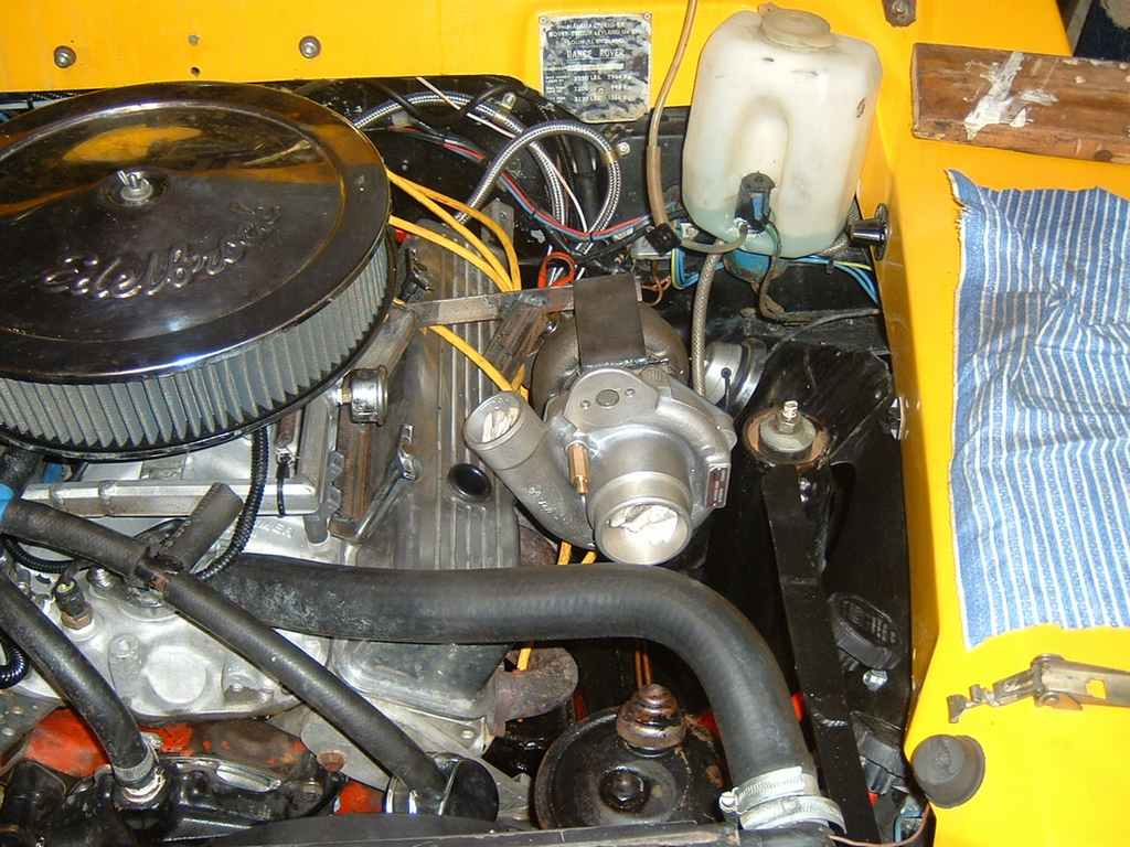
First task was to relocate the power steering reservoir, its now down underneath
the top rad hose. This simple task alone probably took 4-
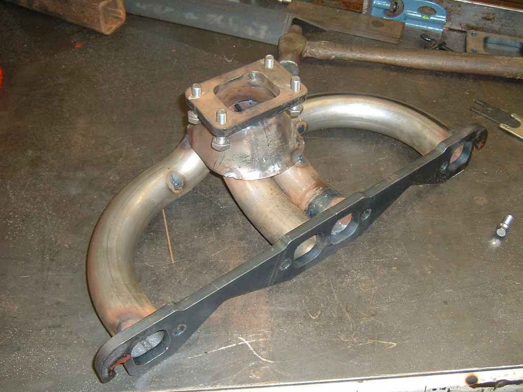
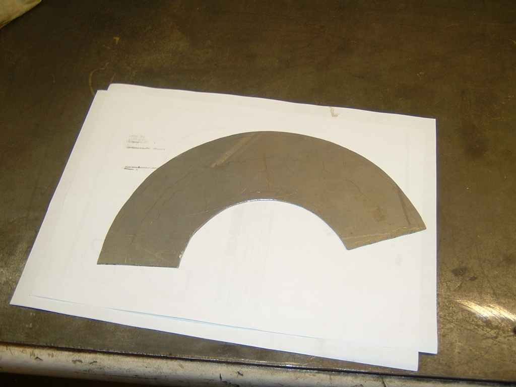
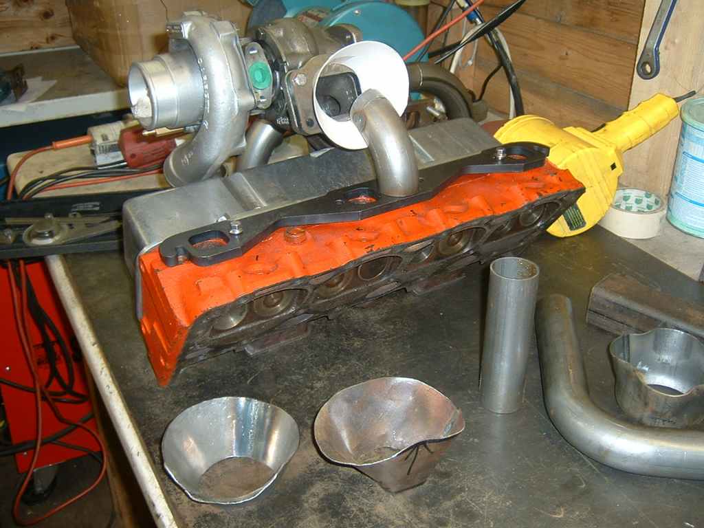
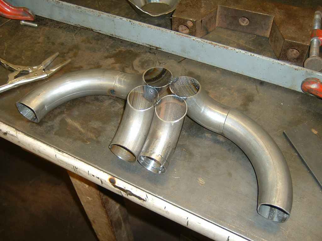
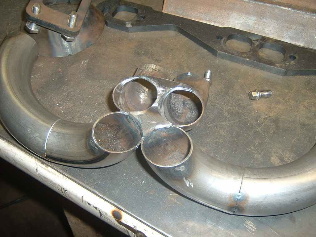
Next step is to create another collector cone. Luckily, I remembered to trace round the first one before folding it up!
Unfortunately after a whole afternoon of figuring, we were unable to come up with a satisfactory merge. The problem on this side is that the turbine inlet cant be arranged at 90 degrees to the exhaust and the turbo is closer to the exhaust flange.
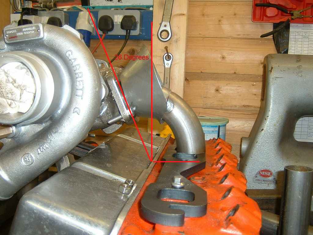
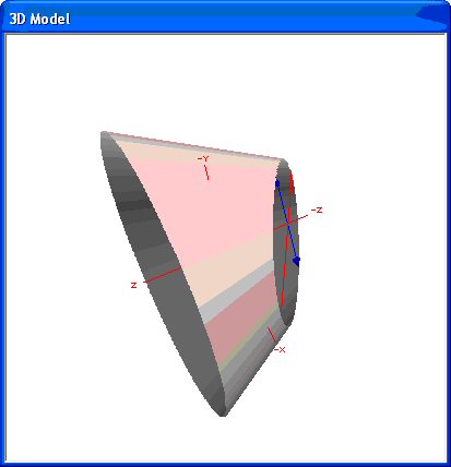
A merge collector is actually called a "frustum cone" i.e. a cone with the pointy end cut of!, I started searching out various spreadsheets and calcs but then I found the perfect tool for fabricating merge cones / collectors. It's called rather appropriately "Cone Layout", available from Pulserate Software It allows you to enter the diameters and length of the collector and then produces a 3d model and a flat template for printing and cutting out. Furthermore, it also allows you to set either end at an angle, so I enter 26' in and solved my turbo alignment problem at the same time!
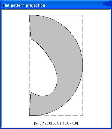
A few printouts and careful cutting and I have the perfect collector template:
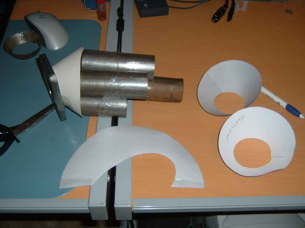
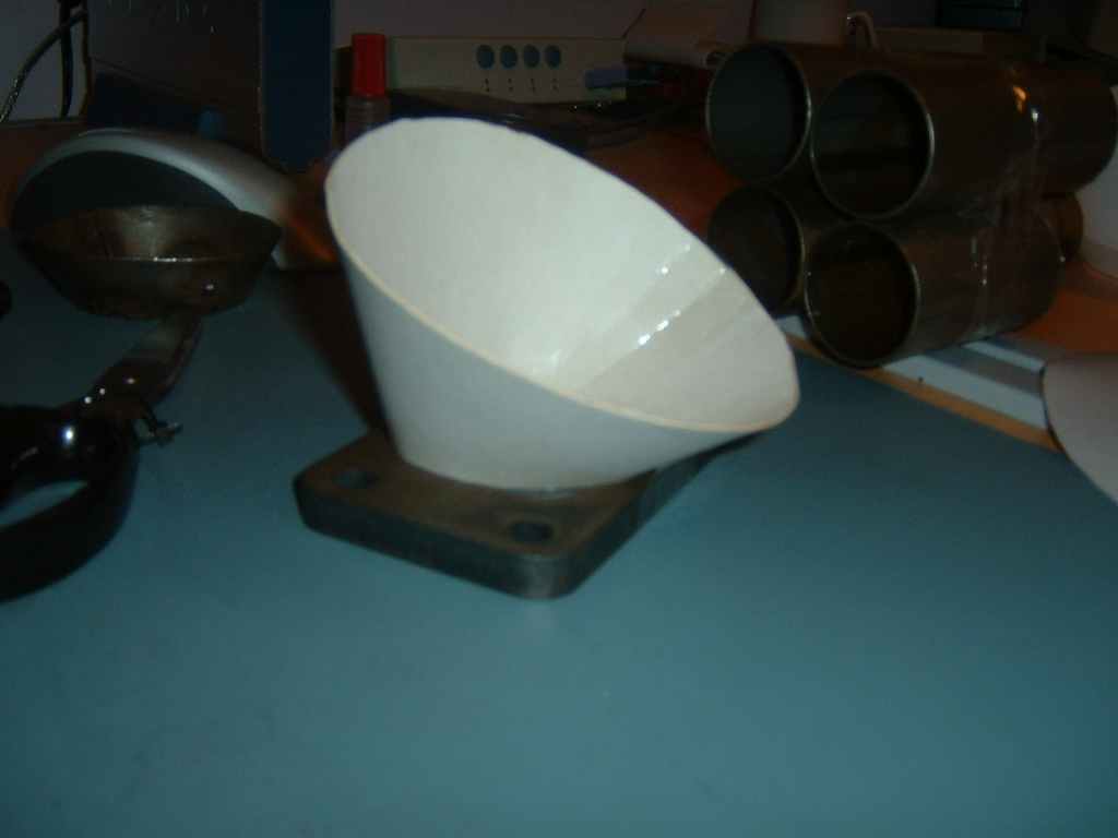
And here's my cardboard mockup, fits perfect!
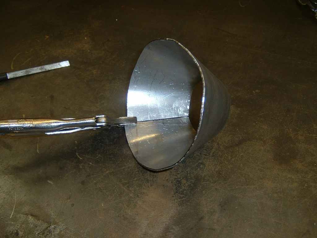
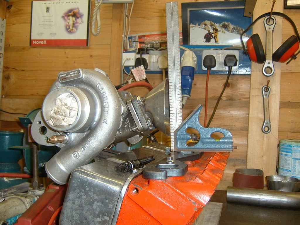
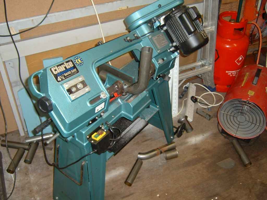
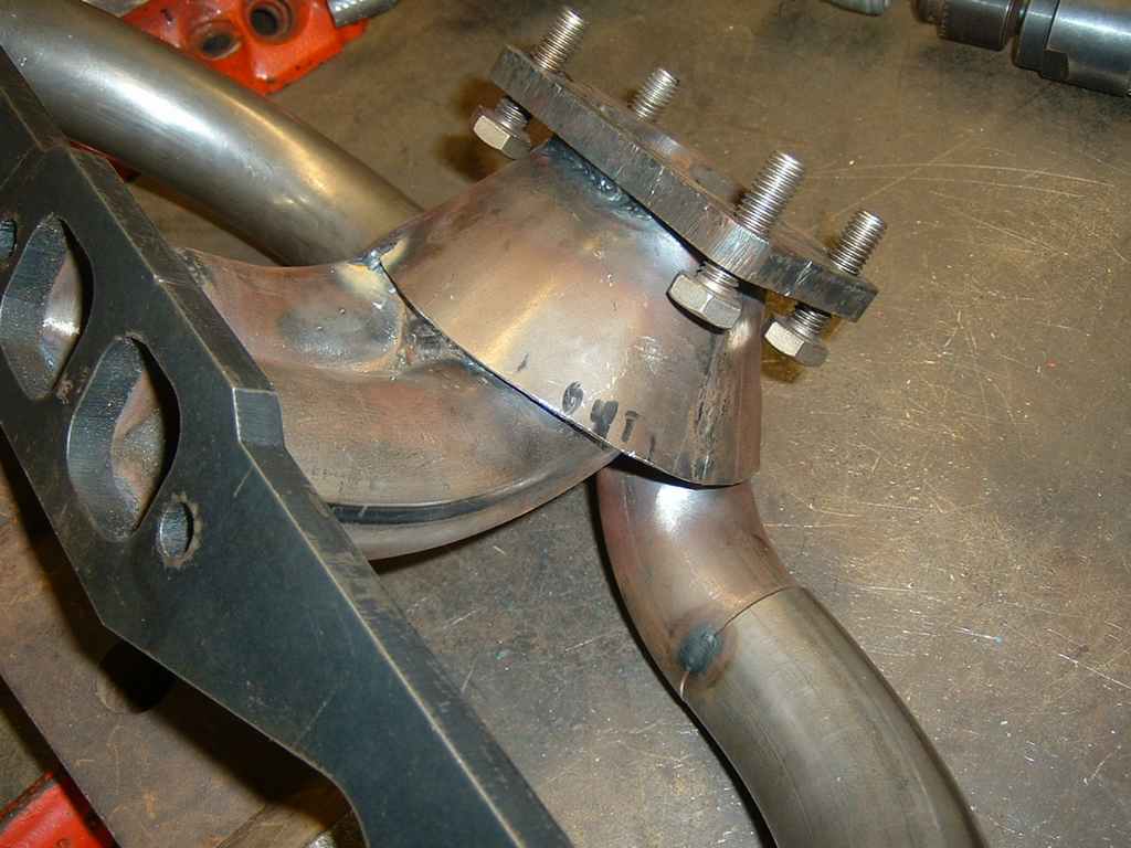
The template was then used to create the same thing in steel, notice that the collector is now 90' to the exhaust flange. Clarke 4" Metal cutting band saw does the job and cuts straight if you take it easy and let the blade cut gently
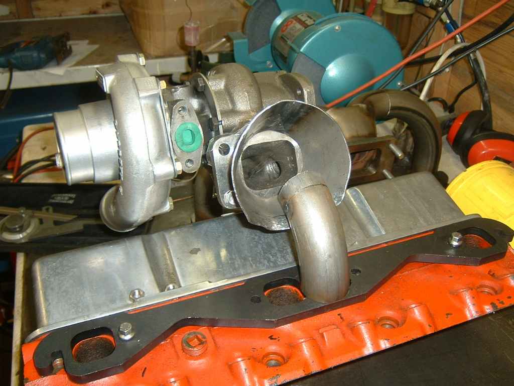
After several more hours of cutting on the band saw I had the near side mocked up.
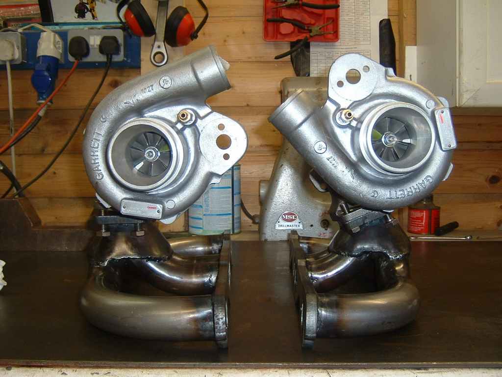
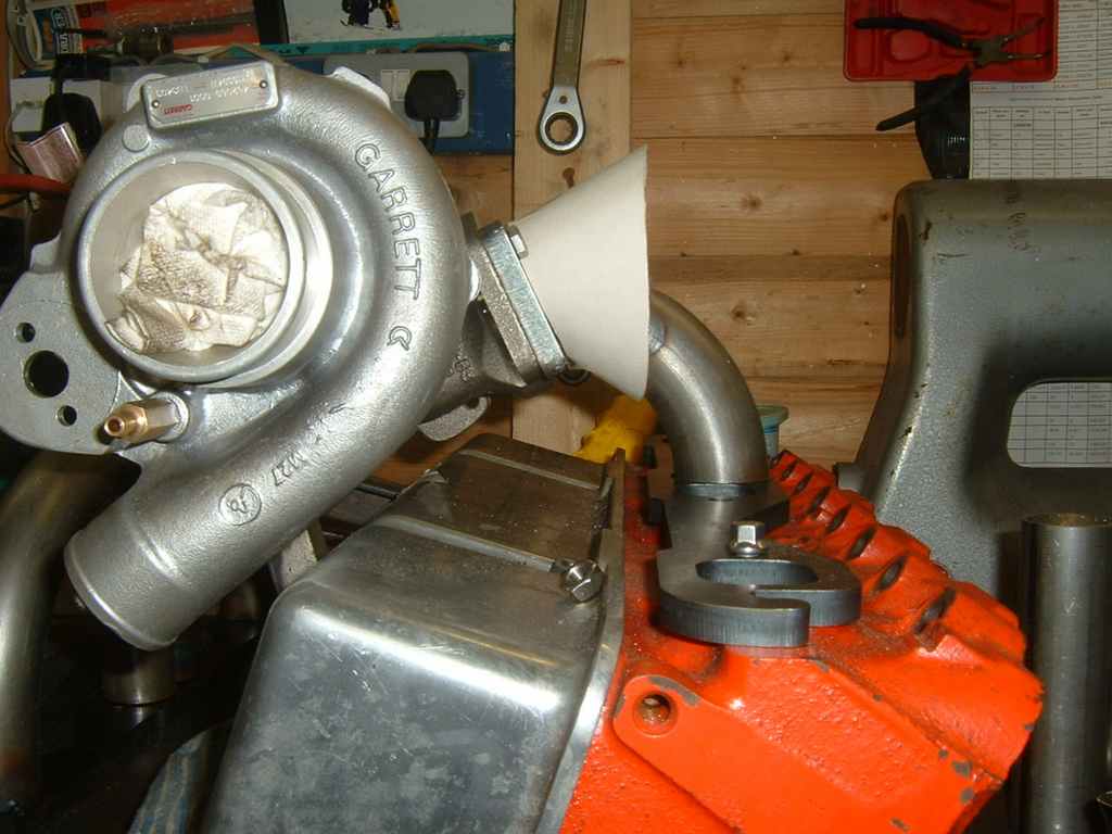
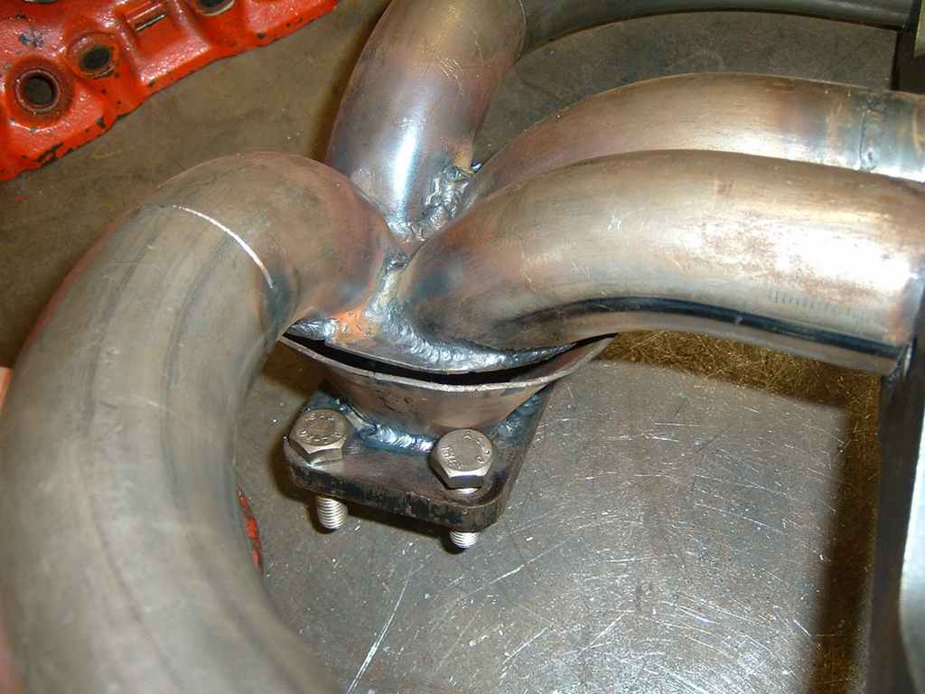
Here's the two mocked up manifolds side by side. The reason for having to cut an angle on the collector can be seen from these photo. Photo angle is taken from bulkhead looking forwards to the bumper (if that makes sense). I'm probably going to make another collector for the other side because i'm not happy with it.

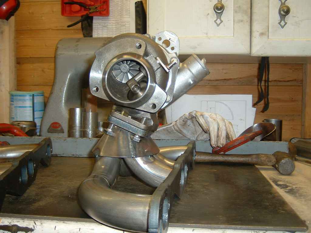
The mockup fitted the car perfectly first time. The offside is shown for comparison.
Now the tricky job of welding it all up properly starts. I made little filler plates and painstakingly welded each one on. What I have since learnt doing the other side is that its easier to make one large plate with four rough holes in it. Weld that to the pipes from underneath, then use a die grinder to open the holes out to the ID of the pipe and then weld from the inside.
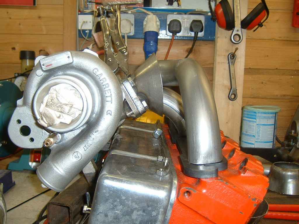
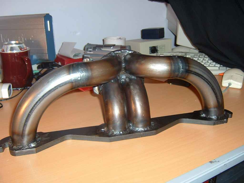
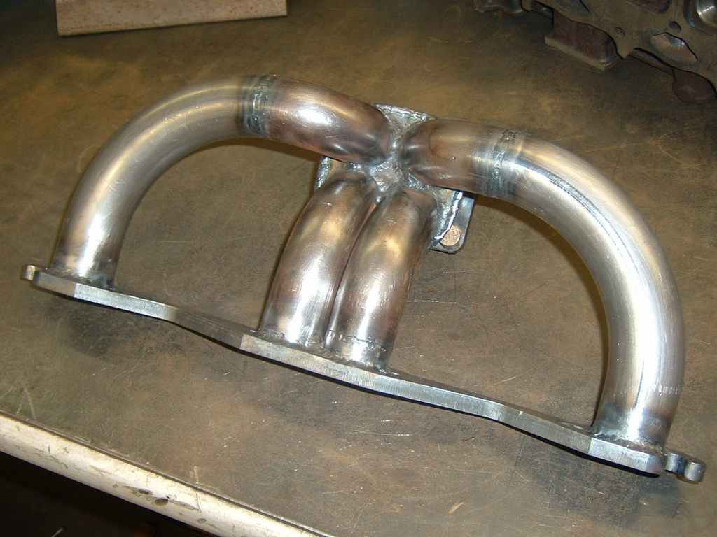
21/2/04 Completed nearside header:
The T3 Flange was bolted to the turbo during welding and the header bolted to a spare head so there's no warpage in either flange.
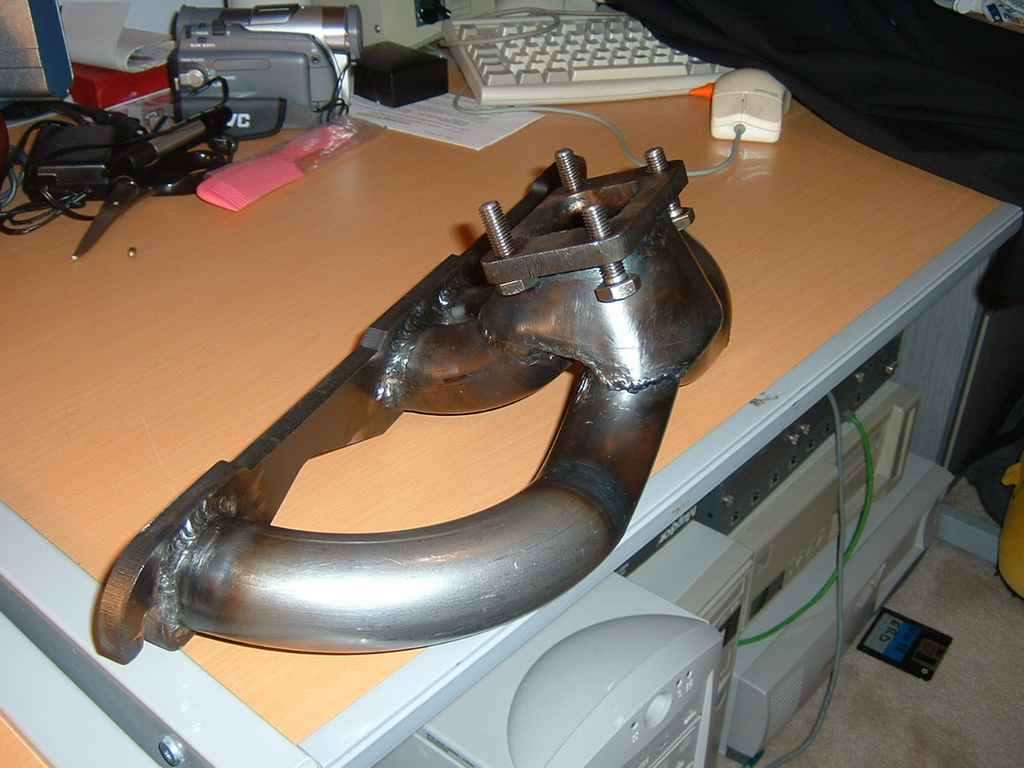
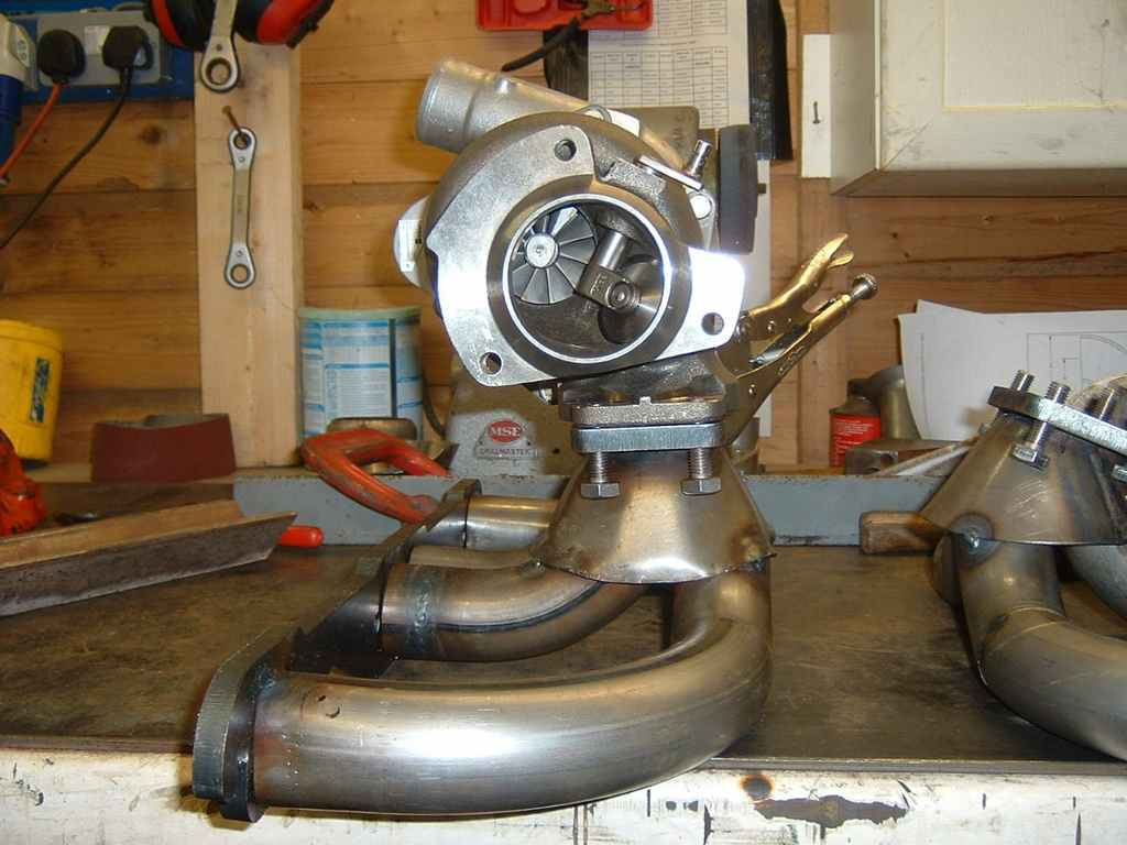
26/2/04 Offside Header Completion
I wasn't happy with the original cone as it had been smashed with the hammer a fair amount to make it fit, so I fabricated a new one using the cone software
Completed header: Not the best welding in the world, but not bad for a first try. Could do with some smaller Tig Ceramics and perhaps a flexible head.
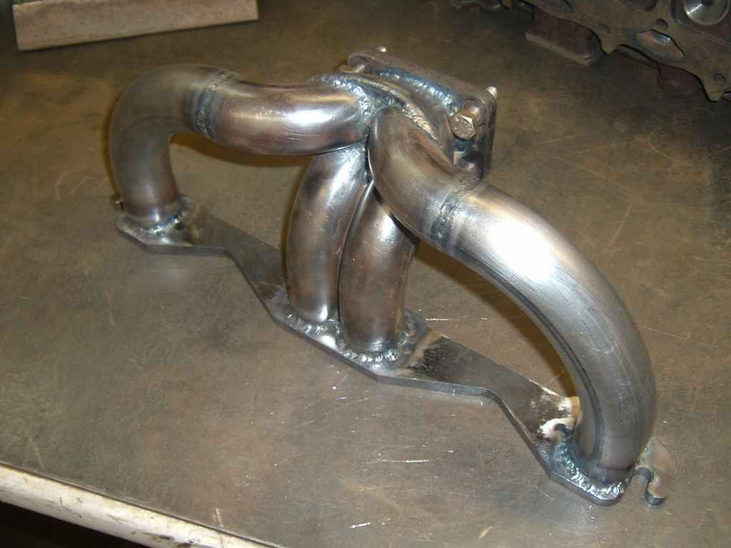
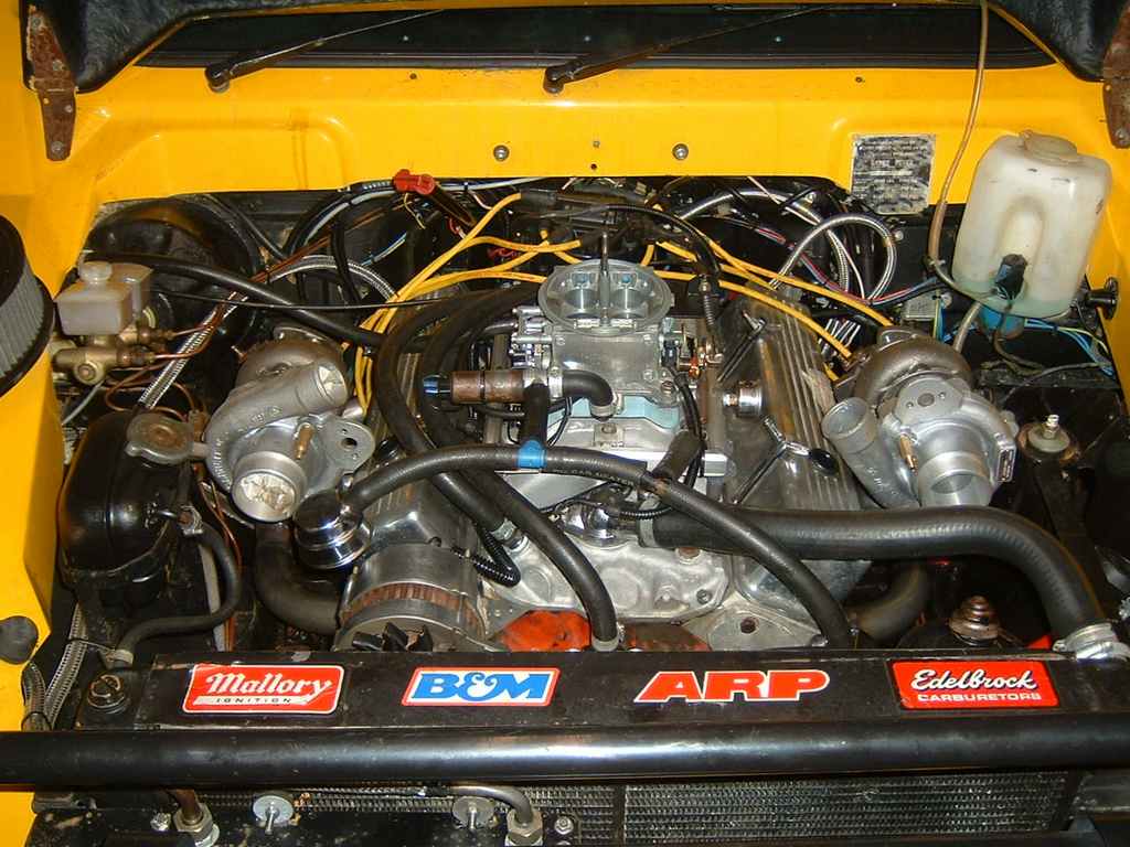
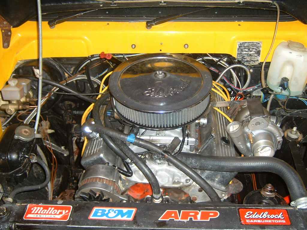
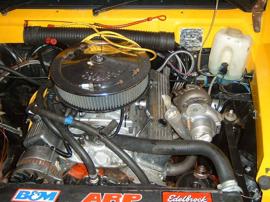
Final Fit!!
Now to finally unwrap the other turbo and try it all out for size: