EAS Reinstatement
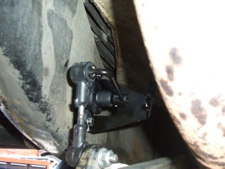
The EAS system had been disabled and completely bypassed. The pipes leading into the air compressor were removed and had std schrader valves fitted on the ends.
A custom loom had also been fitted between a connector on the BECM to force it into thinking the EAS was in manual mode.
At first it seemed reasonable to simply pump each air spring up using a std airline, in practice getting it nice and level was a bit more tricky.
The actual EAS pump looked very new and had been replaced sometime recently. So I
decided I wanted to reinstate the system -
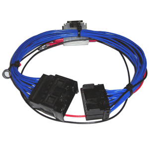
EAS Manual mode loom and manual inflation valves.
See below on how to create one yourself.
To get it working all I did was reverse everything that the instructions said to remove!
- Replace the missing delay timer.
- Reconnect the EAS ECU under the passenger seat
- Reconnect the dashboard switch that sets the level,
- Re-
insert the air pipes into the valve block - reconnect the connectors inside the valve block*
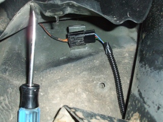
- Remove the EAS bypass loom (blue above) from the BECM.
With all this done, the pump still wouldn’t start. So out with the faultmate diagnostics
-
Commanding various tests like opening valves or running the pump would result in
clicks of relays -
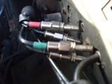
I then noticed that the pump over temp sensor was showing, so googled how to test
the sensor -
With that re-
Then it still wouldn’t run -
So in summary, you need all the doors shut including the tailgate and the engine running for the pump to run.
I don’t actually know why the EAS was bypassed, as apart from replacing the missing delay timer I couldn’t find anything wrong with it.
EAS Fault Message Override
To clear the ‘EAS Fault, slow 35mph max” warning from the dash, put two jumpers on the connector to the ECU:
The EAS computer is under the driver’s seat, screwed to the floorboards. You need
to remove the plastic trim under -
With the cover off you can see the numbers on each wire, using 2 separate jumper wires (just short lengths of scrap wire) connect One Jumper from pin 7 to pin 18 (ground ) The other from pin 25 to pin 1 (+ 12v).
When you startup you will get a soft beep and short “EAS manual” message for a second or two then normal message centre operation will resume.
This will work anytime the ECU is disconnected -
Note: LEAVE THE EAS ECU DISCONNECTED!”
From:
https://www.rover-
P38 EAS Height calibration blocks
Whilst changing the air suspension springs I allowed the offside front Axle to drop down to the floor. I thought nothing of it at the time, but once the car was back together I noticed the car was quite a bit lower on that side.
No problem I thought, little bit of messing around with the EAS will have that sorted out. After spending probably two hours trying to get the car level by measuring from the wheel centre to the bottom of the arch and not really getting anywhere with it, I gave up and decided to have a think and a bit of research. I later discovered that my wheel arch heights are not consistent on all 4 corners.
I came across a discussion and a photo of the proper Land Rover calibration blocks,
tool number LRT60-
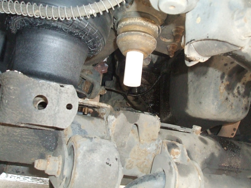
I put the blocks in the bump-
![]()
![]()
![]()
![]()
![]()
![]()
![]()
![]()
![]()
![]()
![]()
![]()
![]()
![]()
![]()
![]()
![]()
![]()
![]()
![]()
![]()
![]()
![]()
![]()
![]()
![]()
![]()
![]()
![]()
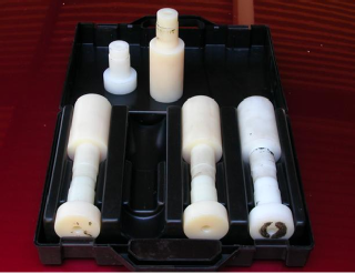

Left: Genuine Land Rover LRT 60-
Far right: my copy (in black)
Near right -
With the 100/105mm blocks fitted, the readings from all the height sensors were almost spot on, with the exception of the front offside sensor. This was at least 10 points out. So I clearly affected the calibration of the unit when I let the axle drop down.
So with the suspension dropped down on the blocks, you simply read the current values from all the sensors and put then back into the saved values. You can see that my offside front is out by 5 steps:
Next I wanted to check the extended ride height -

Motorway (highway) mode is 25mm lower than standard, so I made some new blocks up which were 75mm long. Again, I lowered the car onto the blocks and yet again the front nearside sensor was way out from the other readings which were all within 1 or 2 points of the target.
Access mode requires a 35mm block -
Summary
As noted on the other threads, I also found that the distance from the wheel to the
wheel-
You can use Storey Wilson's software to do these adjustments too.
|
Mode/Length |
Front Block |
Rear Block |
|
Extended |
140mm |
145mm |
|
Std |
100mm |
105mm |
|
Motorway |
75mm |
80mm |
|
Access |
35mm |
40mm |
Update:
Car ended up lop sided again, so I purchased a new height sensor. There seems to
be a few types available -
Britpart STC3579AA -
Easy to fit -