
Range Rover P38 Megasquirt Conversion
As far as I’m aware nobody has tried this out yet. Sure Megasquirt will run a Rover
V8 with no problems -
For example the HeVAC ecu takes the engine speed from the ecu(via the BECM) -
My idea is to fit the Megasquirt in parallel to the existing ECU -
I’m going to do it in two steps -
The setup will be Megasquirt 2 (extra) and Ford EDIS 8. The reason for this is very simple; Its exactly the same setup I have on the Dakar for which I have a complete spare ECU and EDIS module. Which means I have a test bed and known good parts for either car. I need to find out if EDIS8 will run the GEMS ignition coils.
Trigger wheel install
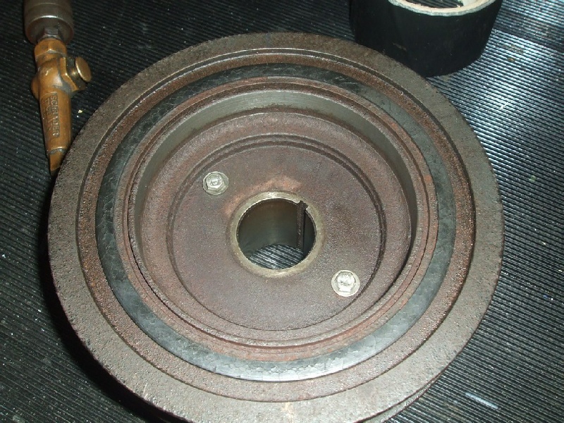
I was originally going to attempt piggy backing onto the OEM crank sensor on the
flexplate, but I had the front in bits for a radiator and a/c condenser change -
Turns out it was pretty easy -
I machined a 51mm shoulder onto the back of the damper and a similar hole on the wheel. The wheel is then held in place with two 5mm bolts through the existing holes in the damper. The are smaller than the existing threaded holes which allows a little bit of wiggle room for adjustment.
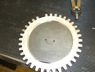
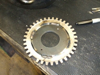
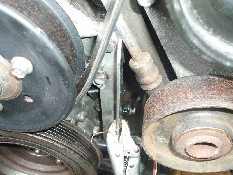
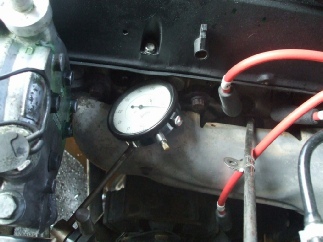
The engine was set at TDC on cylinder #1 using a clock gauge. I then set the missing tooth on the wheel 5 teeth ahead of the VR sensor. This is the standard setup for a Ford EDIS 8 system. The ford VR sensor is attached to a simple bracket made from 1” ally angle. I will need to put some timing marks on the Damper in order to verify my ignition settings.
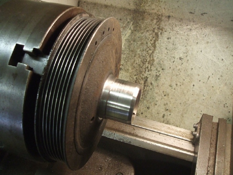
Here’s the wheel in the lathe at about 2000 rpm.
Wiring Loom
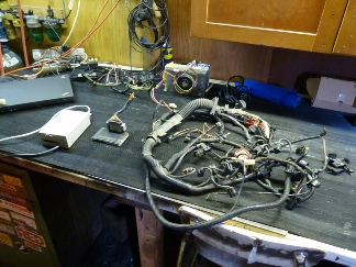
I purchased a secondhand P38 ECU loom of ebay (£30) to use as a basis for the megasquirt loom. The idea was that I would have all the specific connectors for everything on the engine.
This took almost all day to complete -
Sensor Sharing
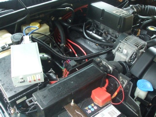
I installed the loom onto the engine and fired the engine up to check that megasquirt
was reading the RPM signal from the edis module -
Reading up on this article explains what you need to do. Essentially you need to remove the bias resistors on the megasquirt, because the existing ECU already has one. Then you need to calibrate the megasquirt with the correct bias resistor and temperature values.
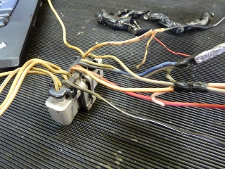
I come up with a slightly easier and potentially more accurate way of doing all this. I used a 20k linear pot which I used to simulate the coolant and Air temperature sensors.
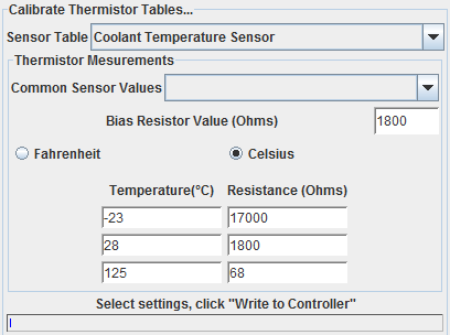
I started with the coolant sensor, I got it to read -
Finally to determine the midpoint reading and also discover the bias resistor value,
I measure the voltage across the pot whilst it was plugged into the connector. You
adjust the pot until you see 2.5v, which is exactly 50% of the supply voltage. I
note the recorded temperature(28’c) and the measure the resistance -
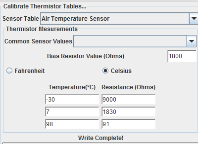
Repeat the same procedure for the air temp sensor and then feed the values into megasquirt (MS2). Here are the values for the coolant and air sensors from a 1996 P38 Gems Range rover
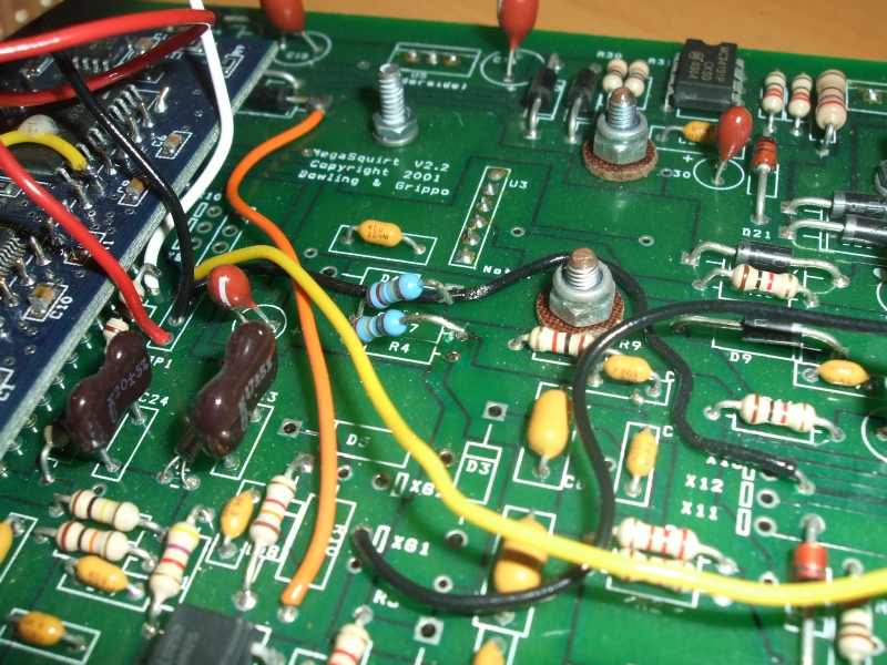
Removing R4 and R7 bias resistors from a V2.2 board.