MegaSquirt and Spark
Wideband Stimulator
I'm now looking at Megasquirt and spark, not only for fuel, but for the added features that it provides such as easy access to target AFR's and selectable openloop mode on MAP I'm using Philip Ringwood’s enhancements to the code
So to test out the wide band target AFR's with the stim i need to modify my stim
to provide a 0-
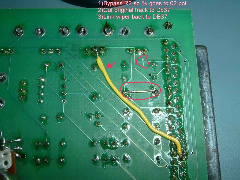
Click here to see modified stim circuit.
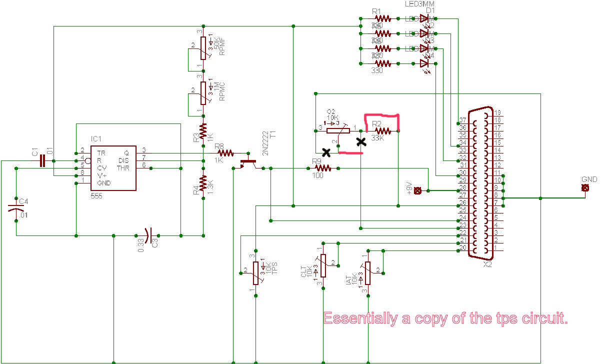
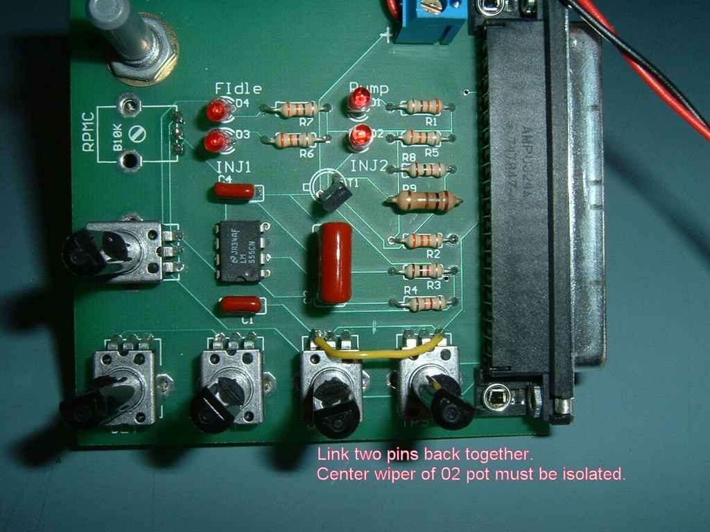
You don’t actually need to remove the POT if you carefully cut the track between the pins.
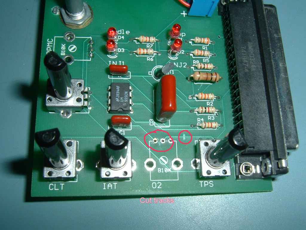
You need to link the track back to the other pot, i used a bit of wire. Then a cut and a link on the back..And now you have a wideband stim!
MegaSquirt and Spark upgrade
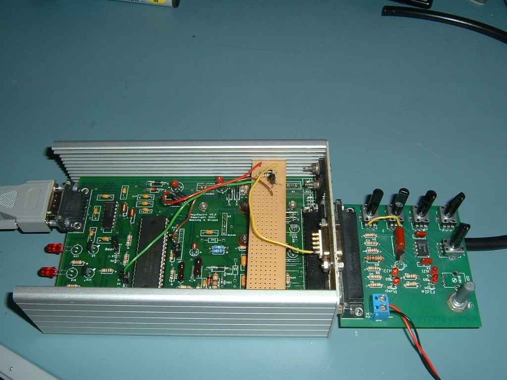
Because MegaSquirt and spark uses the fast idle circuit, and i actually use my Fidle, i wanted to keep it. X4 or X5 can be used, Therefore I copied the circuit onto a bit of bread board and brought the output out via a new DB9 connector. I used a new connector because i dont want to disturb my DB37 harness in the car (because i'm likely to be playing with other outputs too)
HEI Distributor Modifications
Note: This information is quite old now, Version 3 PCB's have VR sensing and Dircect
Coil control using a VB921. Additionally,MSnS-
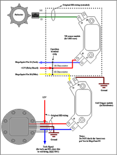
The following diagram and further instructions can be found on Lance's site Also check the following Megasquirt Thread for some great pictures showing what you are trying to achieve.
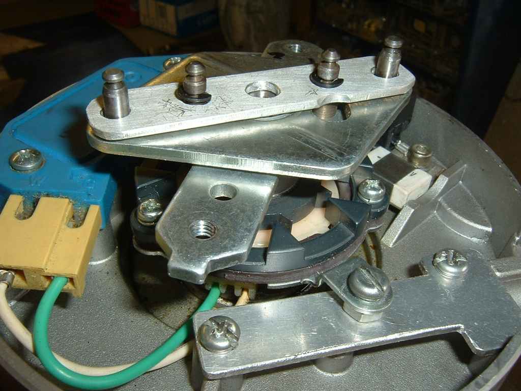
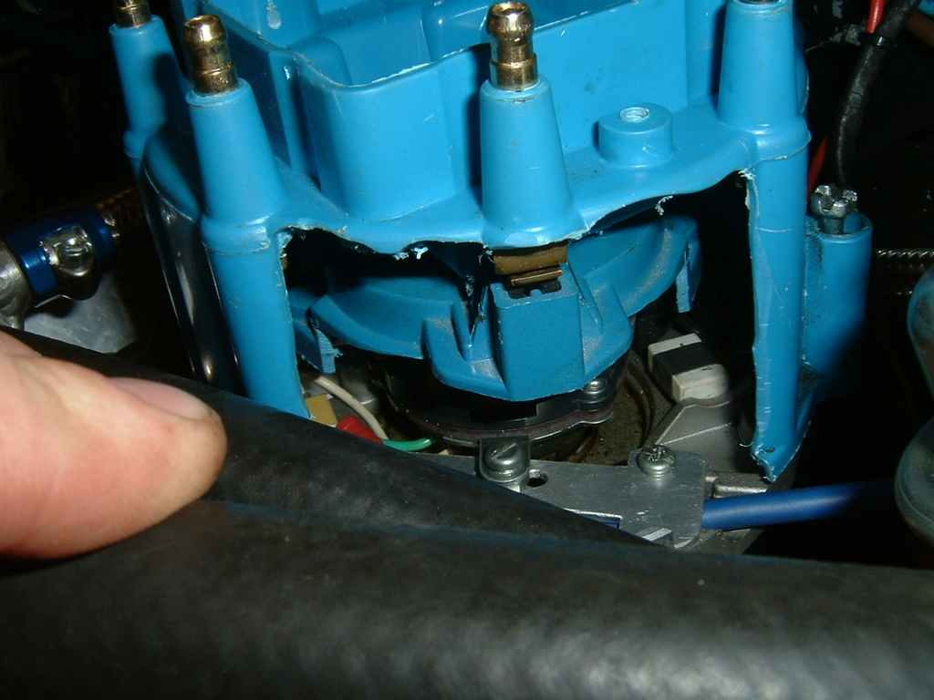
First a quick picture of the dizzy before modifications and a shot after fitting
the lock-
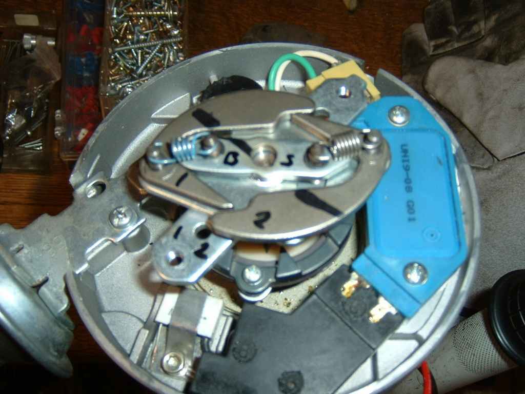
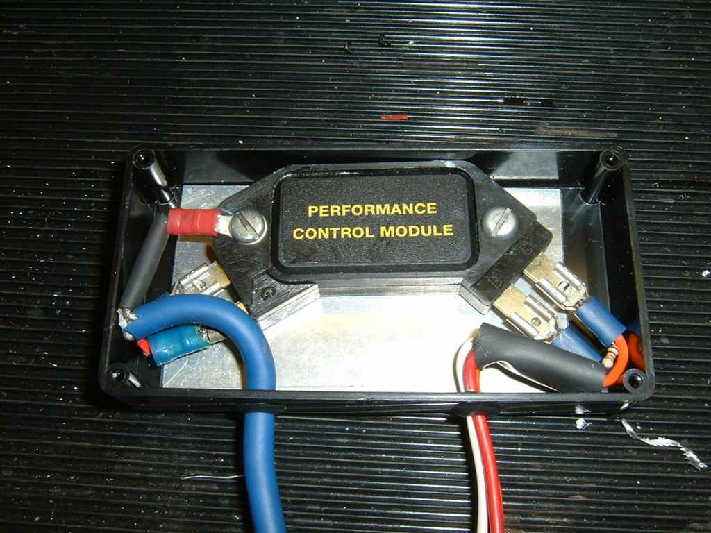
I fitted the second HEI module into a black ABS plastic box on a bit of ally for a heatsink. I want to replace this with a metal case. The extended pickup wires are connected with a bit of shielded microphone cable.
Making a timing tape
Using an adjustable timing light wont work correctly with wasted spark systems such as EDIS. Therefore to check your trigger and rotor alignment correct, you need either a degree wheel or a timing tape fitted to your damper. My Mr Gasket timing tape fell of after one week, so I made another one using visio. You can download the Visio file Here or use this LESS ACCURATE image, which also includes the measurements in MM.
Use this Excel spreadsheet to calculate the figures for other Damper sizes.

Setting it up
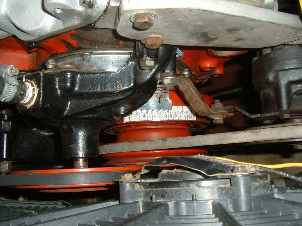
I used the following procedure to ensure that the rotor tip is aligned to the No. 1 tower and the reluctor is correctly aligned at 50+degrees, this requires you to cut up an old HEI cap and rotor arm on the No.1 Cylinder. Note: My No.1 position on my cap is probably different to yours or the factory position (It doesn't matter where it is, as long as its all fitted in the correct firing order)
Set the crank at 28' BDTC (As photo above)
Using your modified cap and rotor, align the tip so that it's in the middle of the
tower -
Now rotate the engine forward one complete cycle (nearly two turns of the crank) until the rotor arm starts approaching the tower again.
Stop rotating when 50 degrees (or your desired trigger advance angle) is met.
Move the trigger plate around until the reluctors align exactly. Mark and drill the hole through the fixing plate to lock it into position.
In your tuning software set the trigger angle to 50' (If that's what you used)
This photo show the rough position of the rotor arm, when the crank is at 50' and the reluctors were aligned.

Finally enter your spark table in the software, reinstall the cap, check your wiring and fire it up.
To check your timing with a light, enter a fixed advance angle -
On my car I saw 0' degrees advance on the damper when it should be showing 10', so I simply changed the trigger angle to 60' degrees and now I saw the desired 10' on the timing light. Once that's complete, set the fixed angle to 0 to get your normal spark table. (You have to use fixed angle when checking with a timing light) I chose this method of calibration because i didn't want to alter the physical alignment of the rotor and the tower (28')
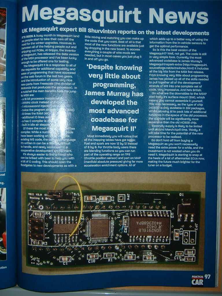
Megasquirt in Print.
Megasquirt is currently being serialised in Practical Performance Car They are fuel
injecting a Vauxhal Chevette and also a 27 litre rover meteor engine -

A Comprehensive list of Megasquirt Links and information: Can be found at the official MSEFI site