
Aluminium Fuel tank Fabrication
14/5/2005
I need a new fuel tank, so thought this would be a good welding project.
First step was to make cardboard template.
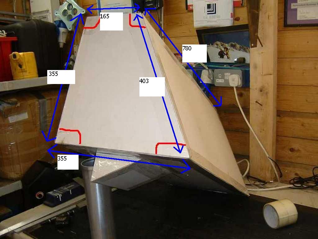
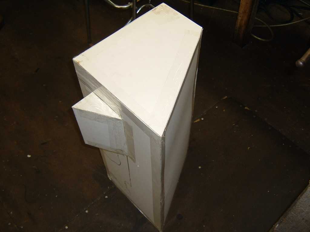
Calculated volume is 71 Litres (15 Gallons)
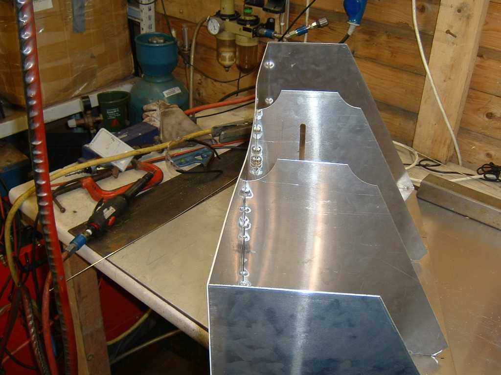
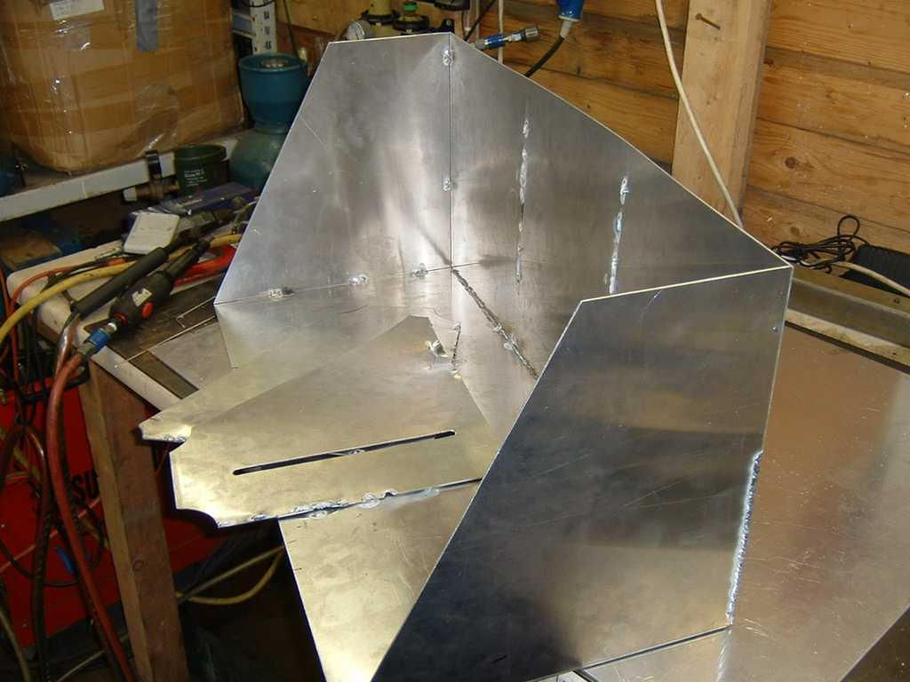
I had all the metal cut to the exact size (14 gauge ns4), just needed to make the baffles.
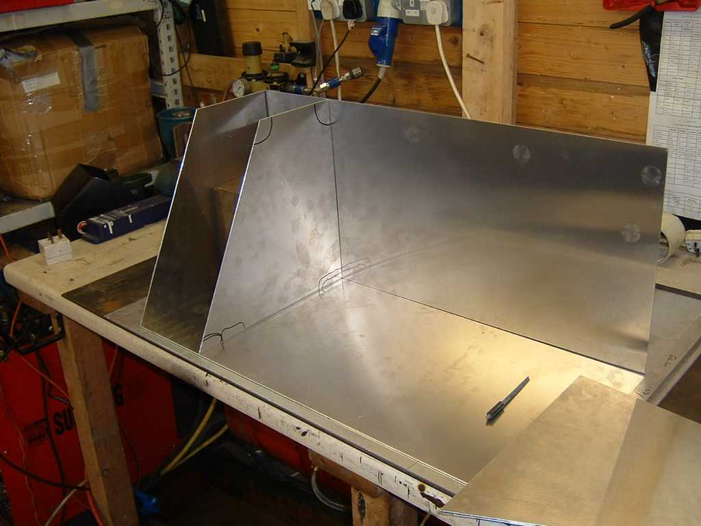
Then things went wrong, the heat from even the light tack welds warped the metal beyond repair.
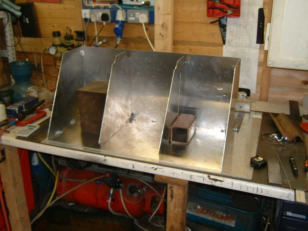
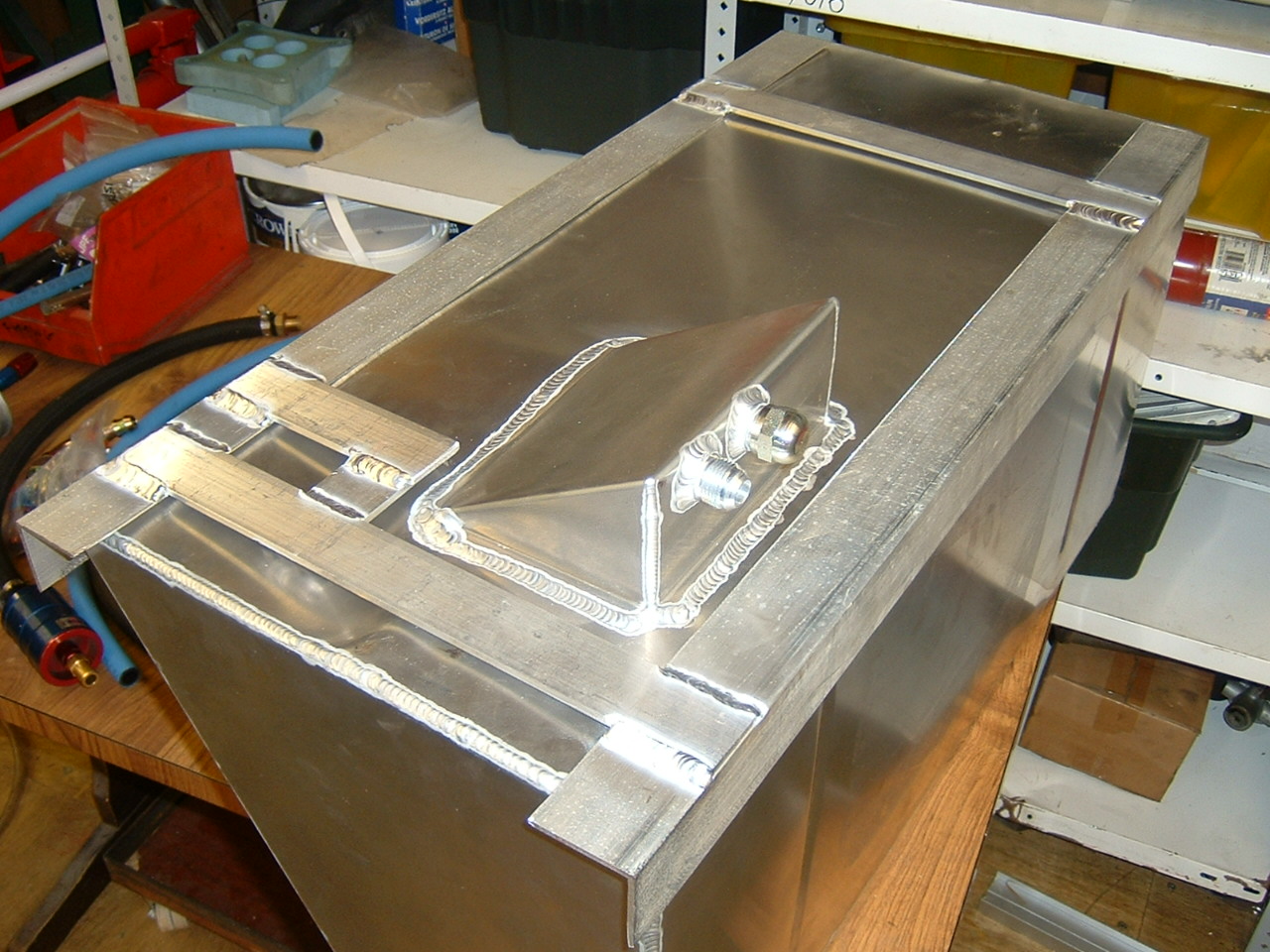
My design includes a sump, so I thought I would see how much the metal warps trying to attach a test piece.
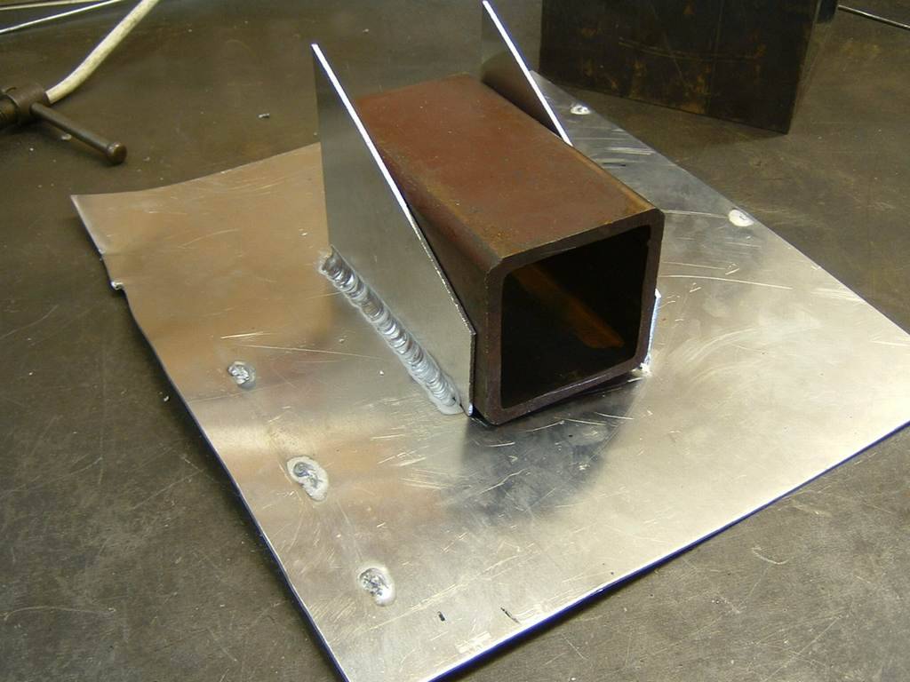
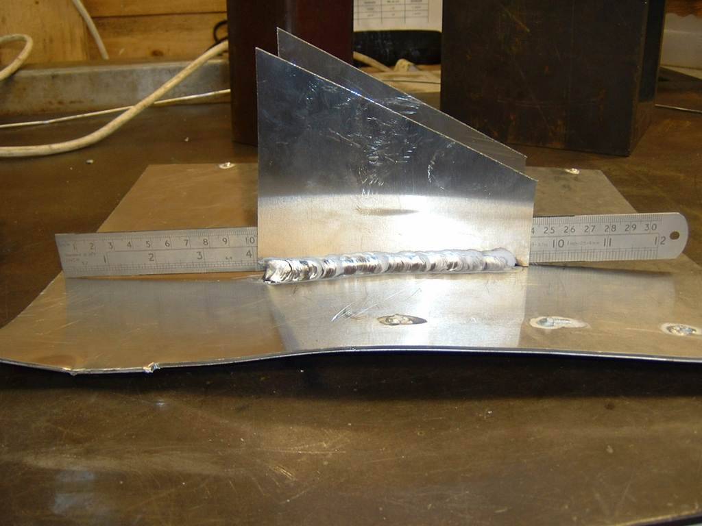
So how do you weld 14 gauge ally without it warping like mad? 6/8/06
Have been quoted £155 to have this made by Bryn at Allyfab, so I thought stuff it
-
27/10/2006
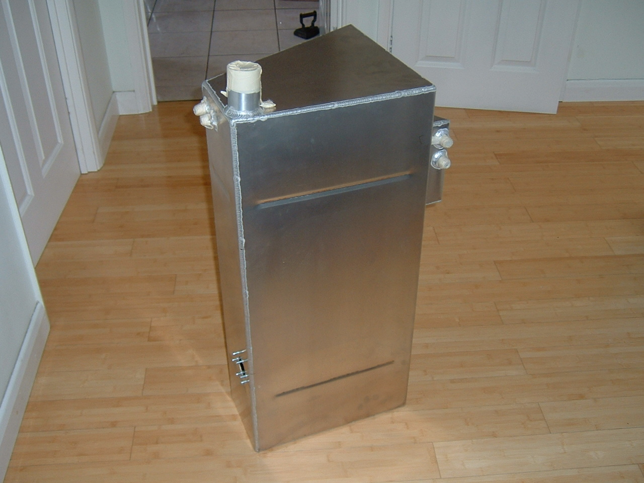
After a considerable wait, my tank is ready. Total cost including a new fuel sender and fuel gauge was £215 delivered. You will notice even this tank has slight warpage near the sump, which makes me feel better!
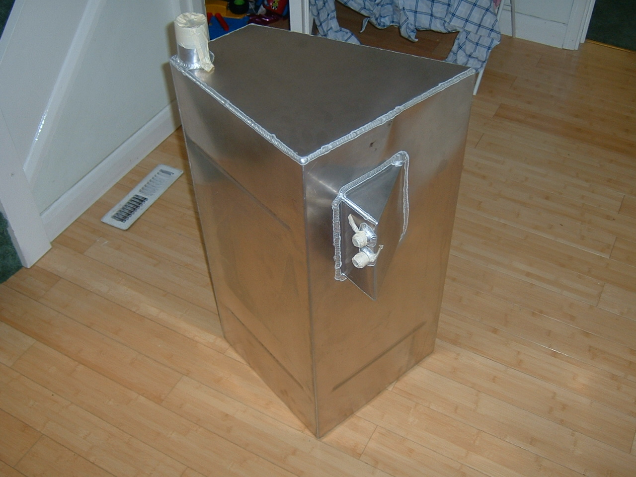
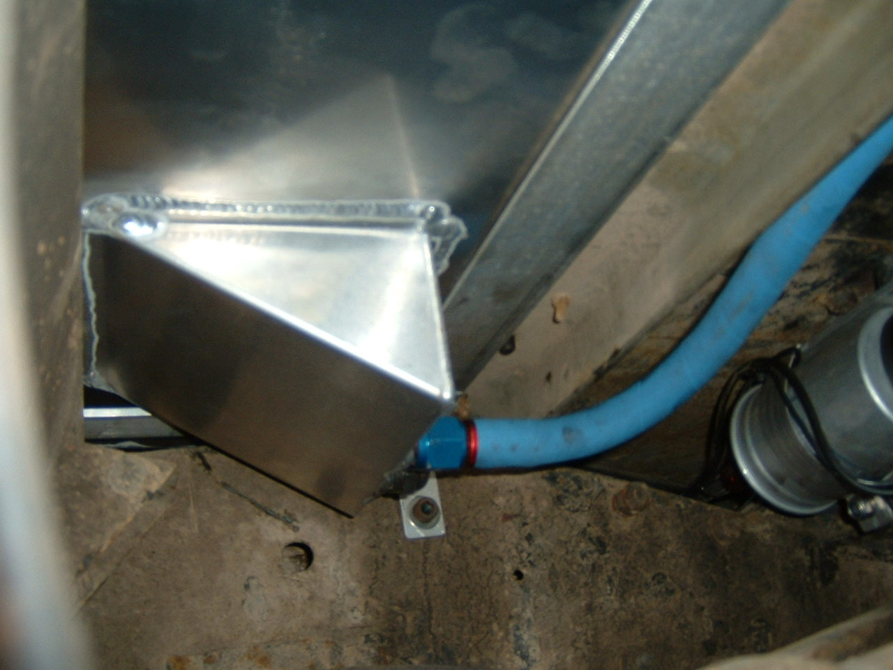
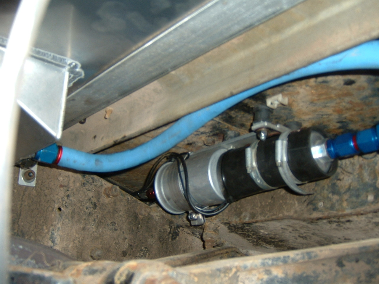
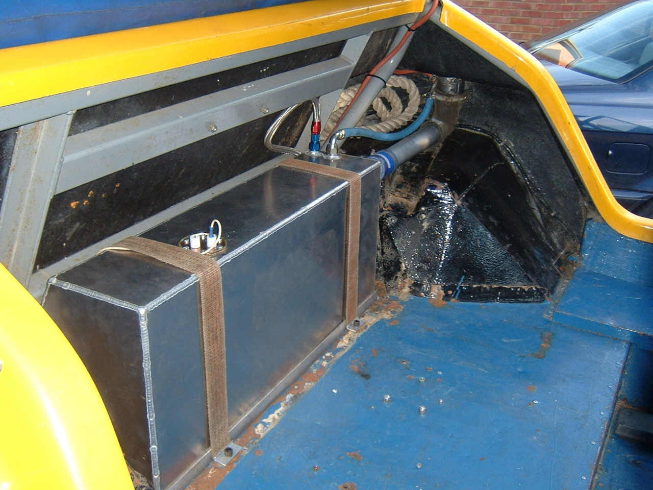
5/11/06 Fuel Tank installation
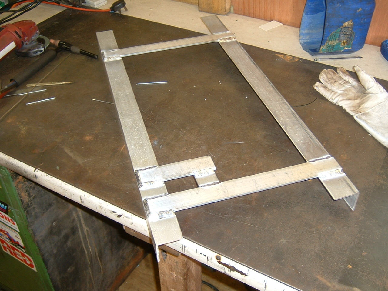
Spent most of the day figuring out and making a cradle to sit the tank on in the back of the car. With the rising cost of electricity, you will interested to know that I used about 5Kw of electricity in about 5 minutes to weld that cradle which is more than the amount of power I consume overnight running my computers, washing machine and dishwasher.
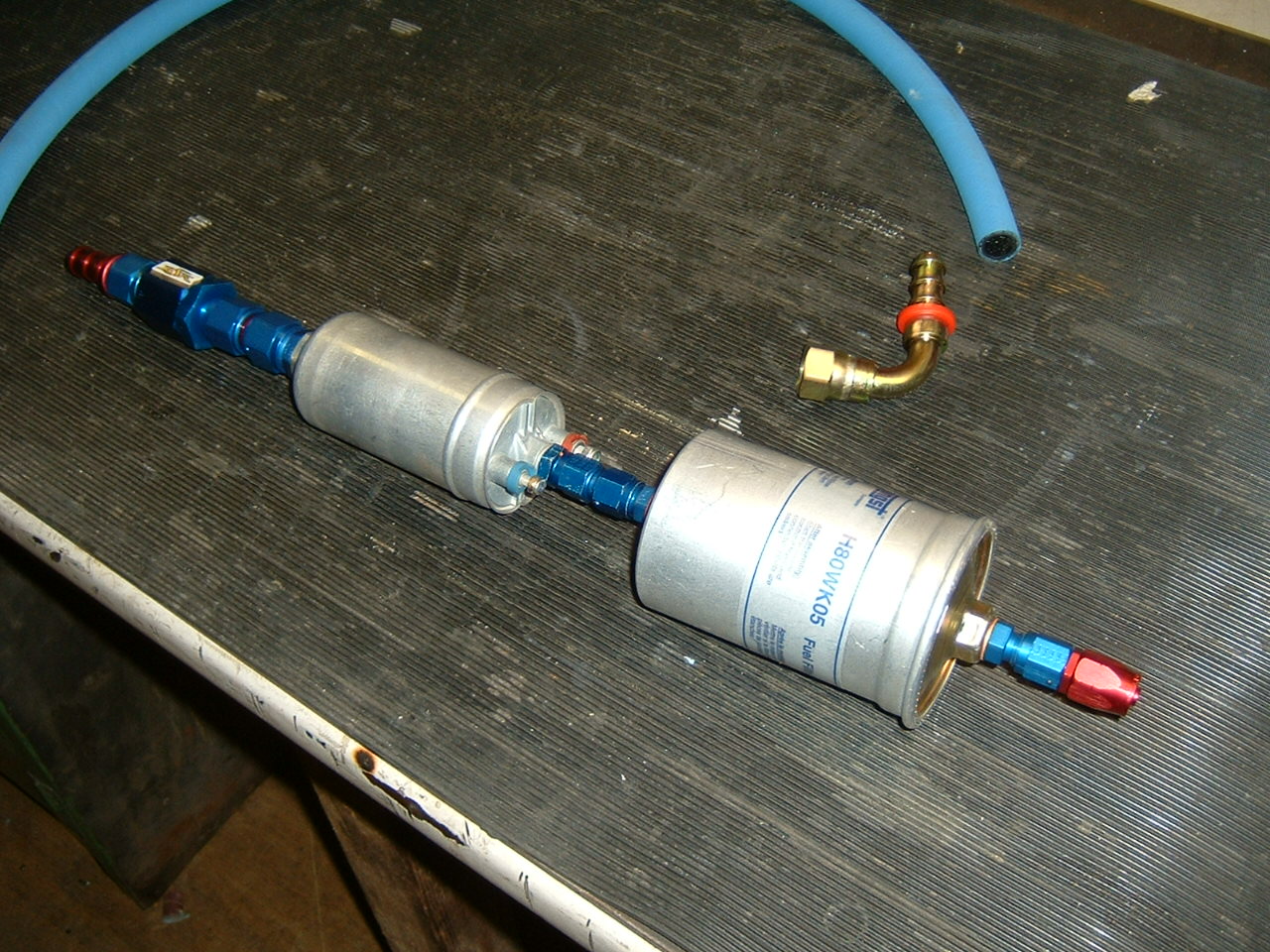
Spent another £150 on plumbing. I elected to use -
Here's the lineup:
-
-
-
-
-
-
-
Bosch "044" motorsport pump
M12x1.5 to -
-
(Above replaced with homemade M12-
M12x1.5 to -
(you could just replace those three with a M12x1.5 to M12x1.5 female/female)
Hengst H80WK05 fuel filter
M12x1.5 to -
-
20/11/2006 Completed
Here's the setup before and after making the little adapter to shorten the overall layout
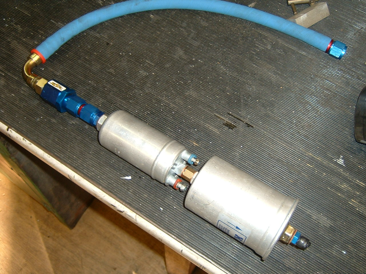
Another few weekends of work and its all completed -
The filler is 2", the breather is -
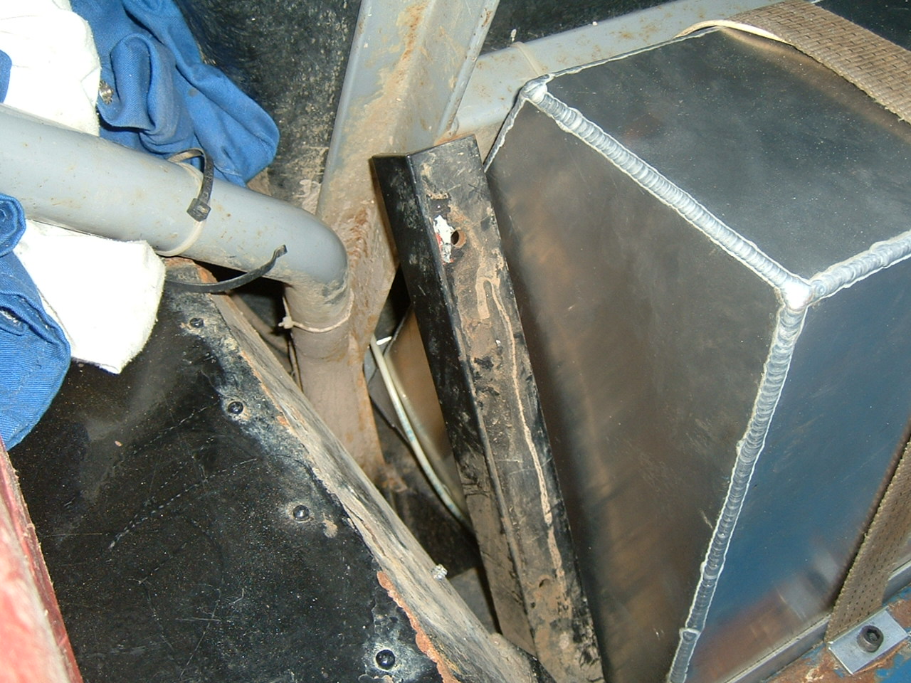
There is a flaw in this design, given that its in a 4x4 -
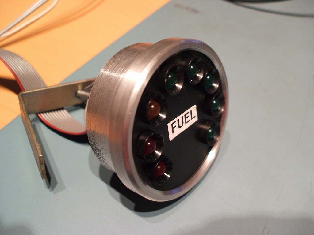
2/1/07 Self Calibrated Digital LED fuel gauge
You may of noticed that my fuel tank is triangular shaped -
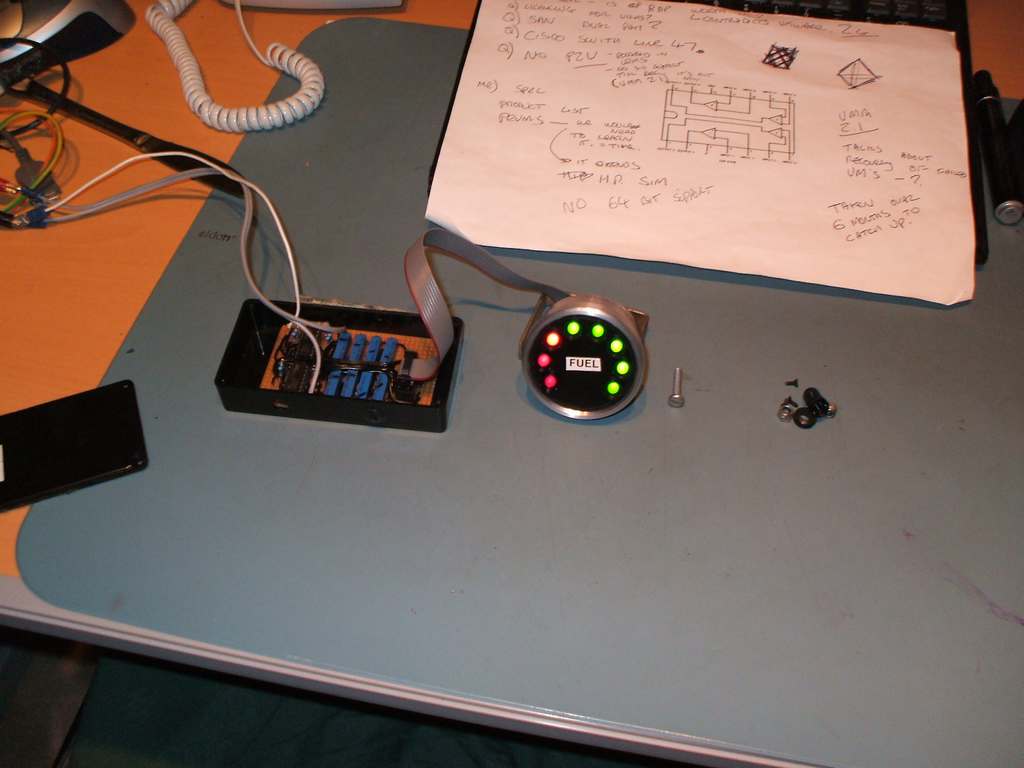
It uses an LM339 comparator which simply compares two voltages -
My tank hold nearly 80 Litres of fuel so I simply went to the petrol station with
an assistant, added 10L of fuel, twiddled the pot until the first LED comes on, then
keep adding fuel in 10L increments -
I made a prototype that used a 5V regulator, but the change in voltage wasn't wide
enough for the LM339 to detect -
I was worried about the lights all flashing on and off as the fuel sloshed around,
requiring some form of electronic damping -
Here's the circuit diagram:
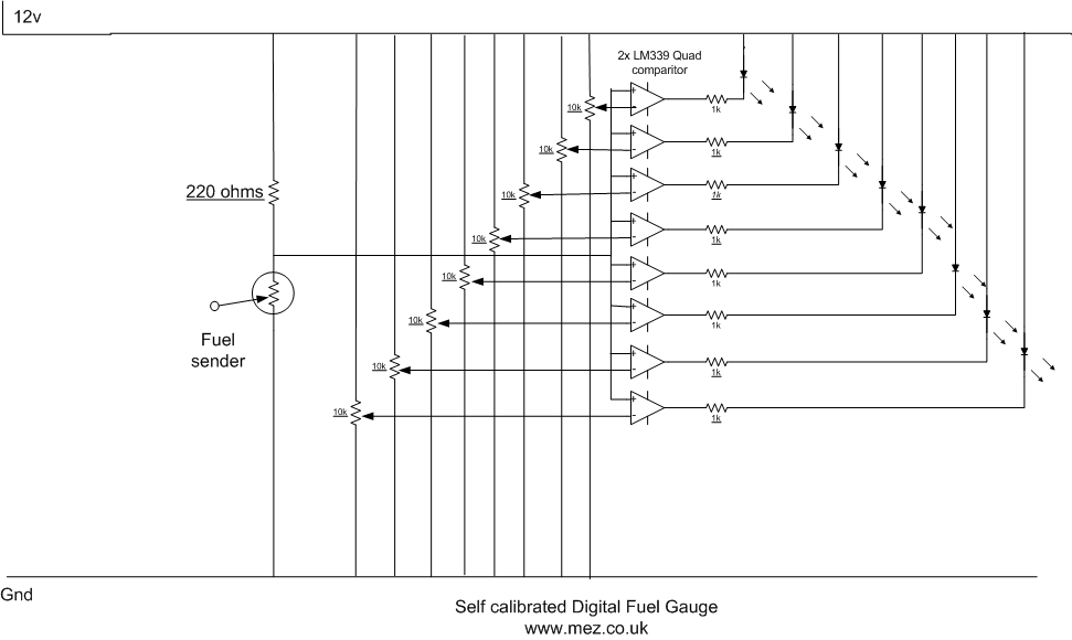
I haven't shown the 12v (pin 3) and ground (pin 12)to going to each of the comparators, The exact pin layout can be found here
Parts List from Maplin:
D220R 2W Res 220R £0.18
2 x UH31J LM339N 0.69 (would also suggest you get some chip sockets, so you can replace and test things without the chip)
UK15R LED Clip Concave 5mm £3.60
WL27E 5mm Red LED £0.34
WL28F 5mm Green LED £1.02
WL29G 5mm Orange LED £0.17
WR49D 18-
The value of the 220ohm resistor may need to be changed slightly, it needs to roughly match the lowest value of your level sender and you dont want too much current going through the sender, I measured mine at a few hundred milliamps.
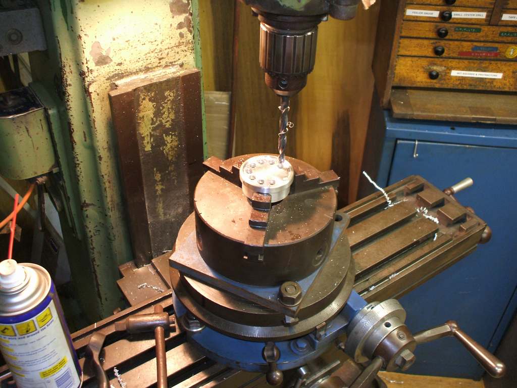
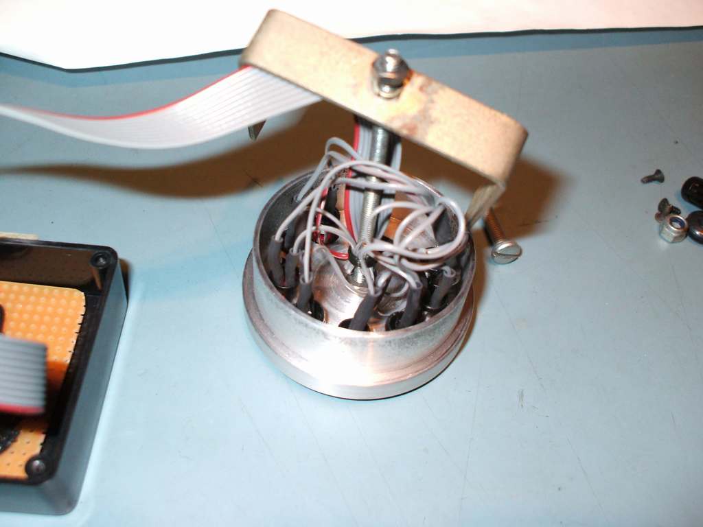
I then needed to get the LEDS into a gauge, original plan was to make a little aluminium
insert to go into a standard smiths gauge -
Circuit needs to go in its own little box hidden behind the dash.
 Here is someone else whos made one for his MEV Rocket
Some discussion about the circuit here
Comments, questions or got answers? Please use the Mez Forums to get in contact or chat about this page.
Next page Edis 8 Conversion